“How does a servo press work?” “What does it mean that it operates with a motor, not air or hydraulic pressure?”
To answer these questions, this article explains the basic structure and operation of a servo press with an illustrative diagram.
Structure of a Servo Press
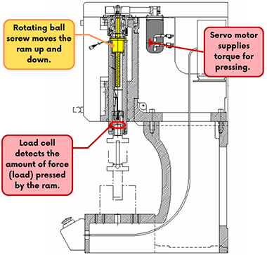
(In the JP Series 5 shown above. In JP-S2 and JP5S Series,
the load cell is built into the upper part of the ram.)
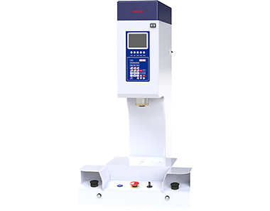
Servo Presse JP Series 5
- When the servo motor rotates, its torque is transmitted to the shaft of the ball screw (shown in yellow).
- The ball screw is a mechanical component which converts rotational motion into vertical (up/down) motion.
- This up-and-down movement causes the guide components to slide vertically in a straight line.
- Attached to the guide is a cylindrical metal part called the ram, which moves vertically in sync with the ball screw.
- A load cell is installed at the tip of the ram to detect the pressing force (load) applied during the forming process.
- Through control of the servo motor's rotation, the ram moves up and down for pressing, while the load cell simultaneously detects the pressing force in real time.
Knowing How a Servo Press Works Contributes to Higher-Precision Processing
The servo-controlled motion and high-precision force detection through the built-in load cell available with a servo press are features not possible with pneumatic or hydraulic presses.
We offer a wide range of servo press models with high precision and durability with various pressing load capacities.
For detailed specifications and application examples, please refer to the following pages.